![]() Apesar de não ter a necessidade, neste momento, de uma fechadura electrónica com código, decidi projectar e construir uma.
Apesar de não ter a necessidade, neste momento, de uma fechadura electrónica com código, decidi projectar e construir uma.
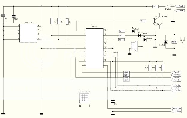
O circuito é bastante simples e inclui uma eeprom 24LC128 para guardar com segurança o código de acesso bem como outros parâmetros de configuração.
Para a saída usei um relé em formato DIP para controlar os habituais electroimans de 24V.
O circuito é alimentado por 6V e possui também um pequeno piezo para indicações sonoras.
A foto seguinte mostra o esquema do circuito.
![]() Although i dont have the need of a code lock gadget at the moment, i decided to design and build one anyway.
Although i dont have the need of a code lock gadget at the moment, i decided to design and build one anyway.
The circuit is very simple and i've included a 24LC128 eeprom to safely store the access code and setup parameters.
For the output i used a DIP type relay to control the usual electrical components.
The circuit is powered by 6V and has a small piezo to output sounds.
The next picture shows the circuit schematic.
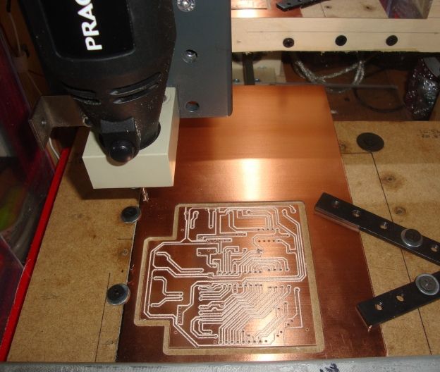
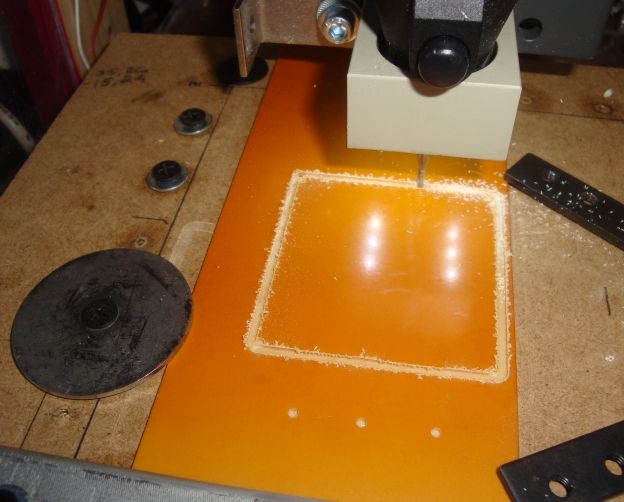
A placa de circuito impresso foi construida na minha máquina CNC caseira.
The printed circuit board was made in my homemade CNC machine.
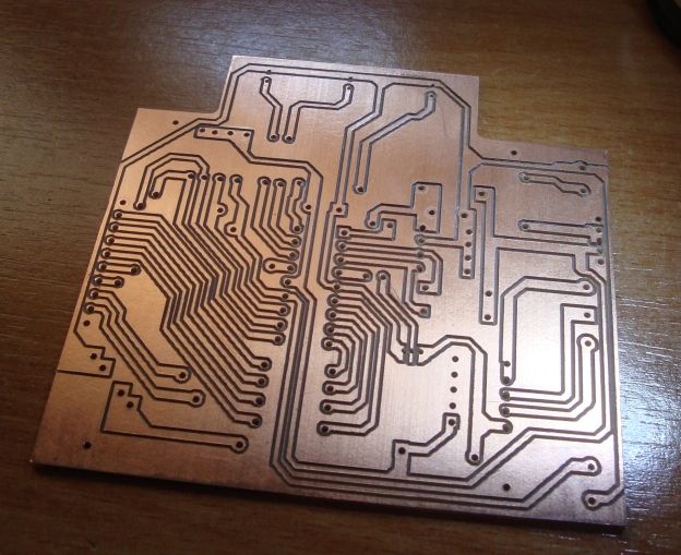
A placa depois de terminada ficou com este aspecto...
When finished, the pcb looked like this...
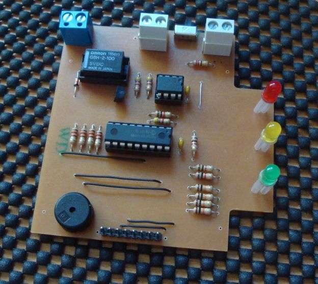
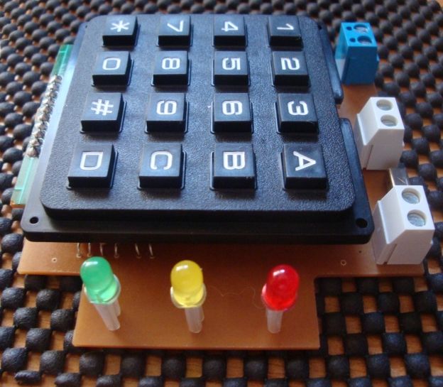
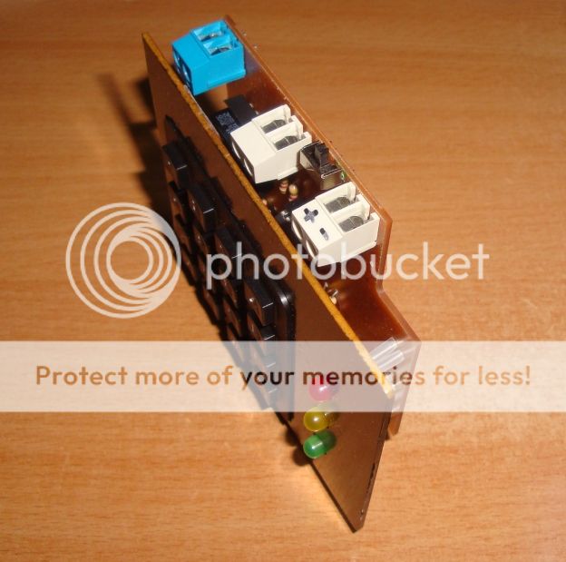
Na foto em baixo é possivel ver os componentes já soldados na placa de circuito impresso.
The picture bellow shows the components soldered on the pcb.
O teclado ( keypad ) encaixa nos terminais e fica a poucos milimetros de tocar nos integrados.
The keypad connects to the header terminals and stays above the dip components by just a few milimiters.
Como tinha algumas placas de baquelite ( sem camada de cobre ) decidi cortar um pouco para fazer um pequeno frontal e ver como fica o aspecto final.
Since i have some bakelite boards ( without the copper layer ) i decided to cut a small piece to work as a front panel and see how it would look like.
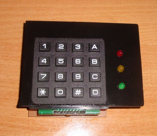
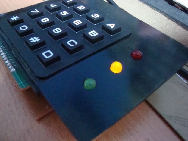
Depois de cortada e pintada a placa de baquelite é este o aspecto do circuito.
After it was cutted and painted the bakelite board was placed on the circuit.
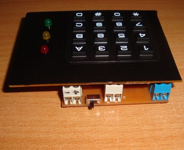
Também os terminais ficaram a alguns milimetros de tocar no frontal...perfeito !
The terminals also stayed bellow the bakelite board by a few milimiters...perfect !
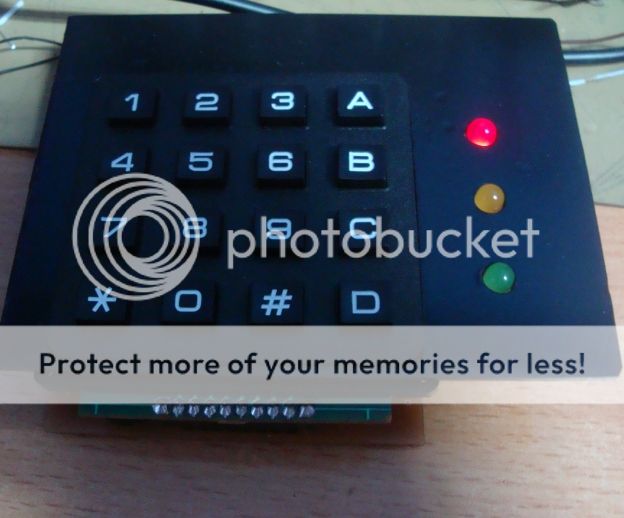
De outro ângulo...
From another angle...
Uma vez ligado o circuito, ele executa uma inicialização onde acende os 3 leds e verifica o estado da eeprom.
Se tudo estiver ok ele entra em espera acendendo o led amarelo.
When powered on, the circuit will initialize. It will light up all three leds and checks the eeprom.
If everything is ok it will enter a standby mode and have the yellow led on.
O código de 4 digitos pode então ser introduzido. Caso o código não seja igual ao código memorizado na eeprom ele acende o led vermelho e o piezo tocará um som de erro.
The four digit code can now be entered. If the code is not the same as the one saved in the eeprom it will light up the red led and the piezo will play an error sound.
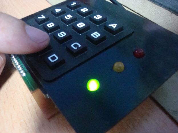
Caso o código introduzido seja o correcto, o led verde acenderá e o relé é activado durante 2 segundos.
In other hand, if the code is correct, the green led will light up and the relay will trigger for 2 seconds.
O código de acesso pode ser alterado em qualquer altura e sem necessidade de desmontar o circuito.
Para isso basta carregar em *, sequência de 2 digitos e #. Esta sequência de 2 digitos é programada directamente no ficheiro Hex.
Depois de introduzida a sequência, o circuito entra no modo de programação onde podemos introduzir um novo código de 4 digitos.
Depois de introduzido o código, o led amarelo pisca para re-introduzirmos o código novamente para confirmar.
Caso o código esteja validado correctamente o led verde piscará durante uns segundos e automaticamente sairá do modo de programação.
The access code can be changed anytime and without the need of removing the circuit.
To change the access code we must press *, 2 digit sequence and #. This 2 digit sequence is programmed in the Hex file.
After entering the sequence, the circuit will start it's programming mode and we can type the new 4 digit code.
With the last digit entered the circuit blink the yellow led. This means that we must enter the new code again to validate.
Once validated the green led will blink for a couple of seconds and return to standby mode.
Também é possivel escolher o tempo em segundos que o relé ficará activado após a introdução do código correcto. Para isso existe uma diferente sequência que depois de introduzida permitirá ao utilizador carregar nas teclas de 1 a 9 ( 1 a 9 segundos ) para memorizar o tempo.
Tanto o código como o parâmetro tempo do relé é guardado na eeprom e não perde os dados mesmo que o circuito perca a alimentação.
O circuito também possui uma saída UART onde é possivel recolher toda a informação do circuito, desde a inicialização e estado da eeprom até aos códigos ( ou tentativas ) introduzidos.
It is also possible to choose the time in seconds that the relay will stay triggered when valid access code is entered. For that there is also a special sequence that when entered will allow the used to choose the time in seconds by pressing keys from 1 to 9 ( 1 sec. to 9 sec. ).
Both time and access code are stored in the eeprom. Data will not be lost even with power off.
The circuit also has a UART output where it's possible to record all the initialization information and pressed keys.


