TEVO Tarantula Prusa i3 3D printer
![]() Recently i had the oportunity to assemble and review a 3D printer. This is the TEVO tarantula prusa i3.
Recently i had the oportunity to assemble and review a 3D printer. This is the TEVO tarantula prusa i3.
NOTE: -> The step by step videos are available at the end of the page.

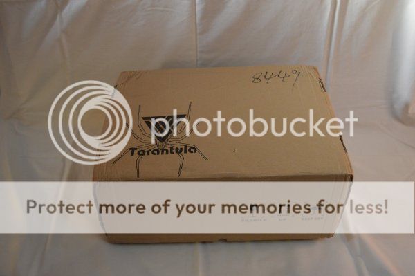
The package arrived in just a few days since it was delivered by Fedex.
However it was stopped in customs and it was requested the CE document.
The seller sent the document by email and the package was cleared.
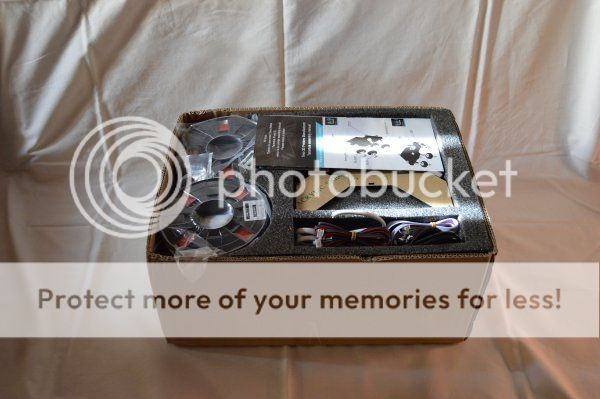
Opening the box, we can see that everything is well packed with foam. Inside, as announced, there was the 2 PLA filament rolls.
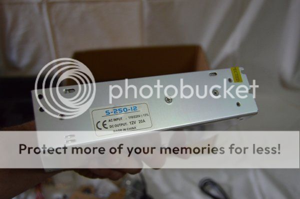
The power supply is a x3 12V and 20A output.
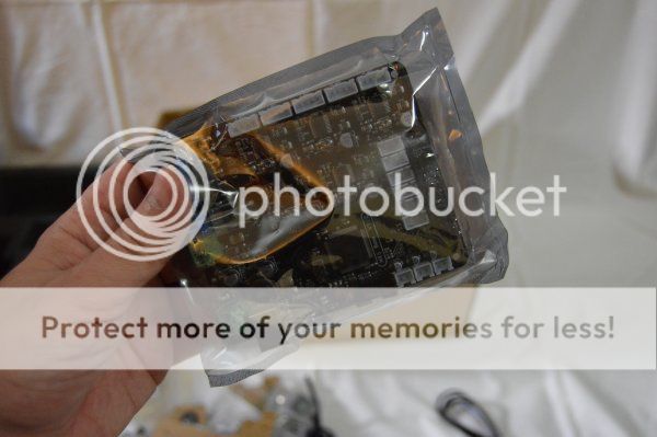
The controller board is very compact. It includes 5 Allegro A4982 smd stepper motor IC drivers.
The main chip is an Atmel ATMEGA 2580 microcontroller.
It also has 6 inputs for endstops (x+,x-,y+,y-,z+ and z-).
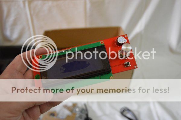
To control the printer there's a board with a 4x2 LCD, one piezo, one rotary switch and a small tactile switch for reset.
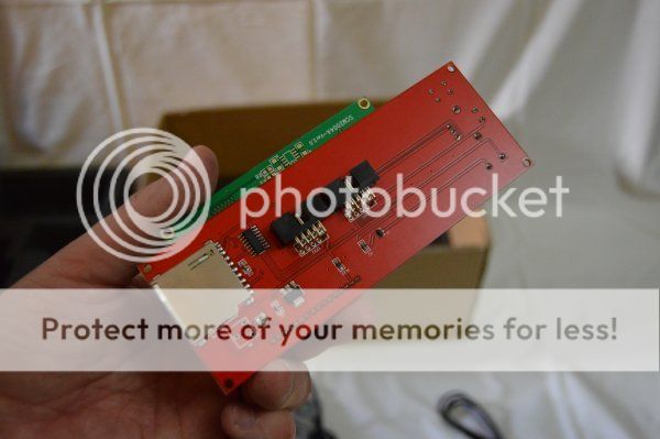
At the back side there is a SD card slot.
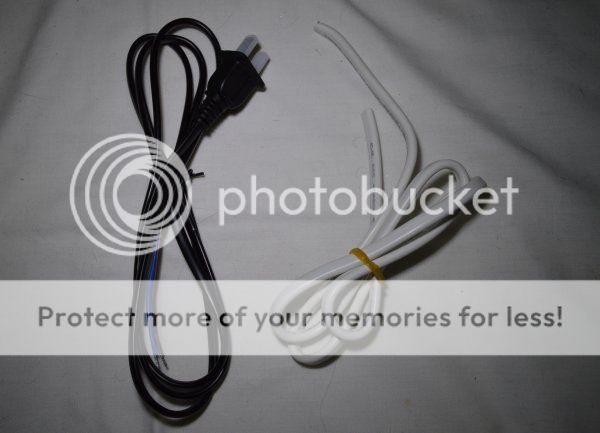
At the purchase moment, the seller mentioned that the power plug model was selected according to the destination address.
However, in this case, the seller should deliver an european plug but instead he sent an US plug.
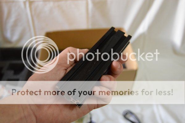
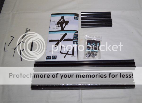
The frame structure is made from aluminium 2020 and 2040 profiles painted in black color.
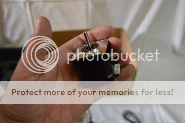
4 small steppers are included. 3 stepper motors for the axis (X.Y and Z) and one for the extruder to push/pull the filament.
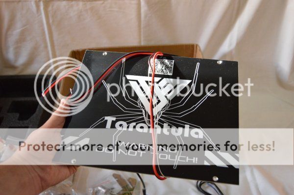
There are 2 table sizes available. This one is the upgraded version with a bigger size table (200x280).
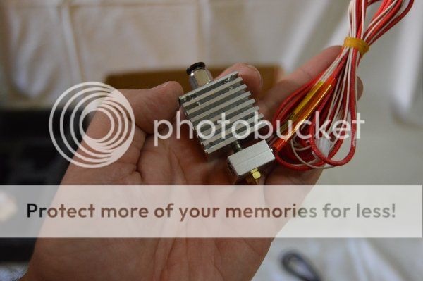
The heatsink part came with many debris inside from the cut process.
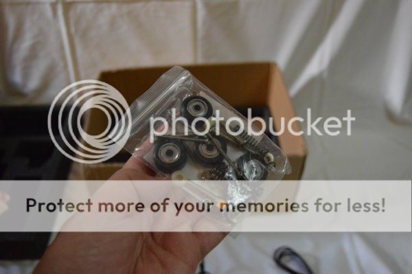
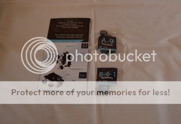
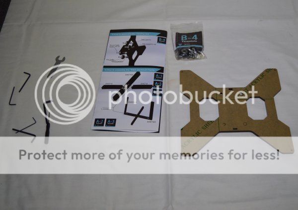
All the parts come inside plastic bags separated and labeled by steps.
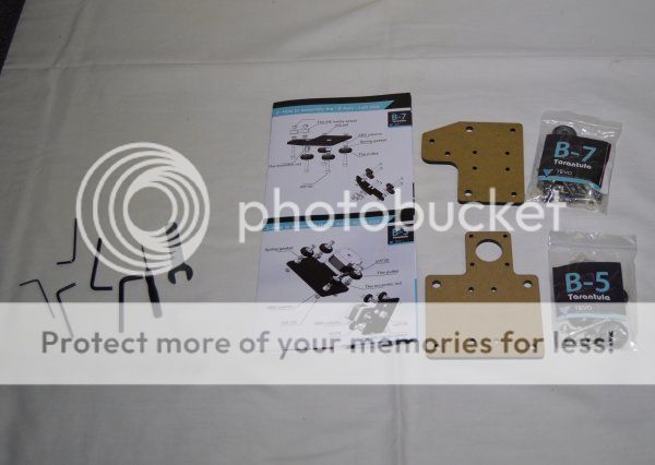
There is also a small bag with some tools to help build the printer. However, the small allen key that is used with the L connectors should not be used because in my case it was a bit too small and was damaging the screw.
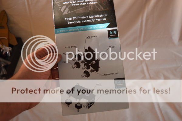
The assembly instructions is just a single folded sheet.
At the beginning it looks very detailed with the exploded view images and labeled parts but in fact it is very incomplete since it does not explains the assembly of some of the parts like the extruder, endstops and there is no reference of how to do the calibrations. There are also some assembly errors.
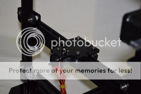
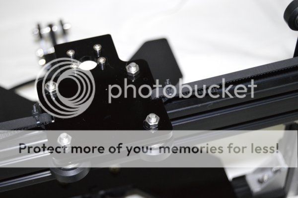
The first step in the manual is the X carriage and for this step we need bags A-9 and B-6-1.
Because i was so curious to test this axis system, i picked up a frame and tested the moviment.
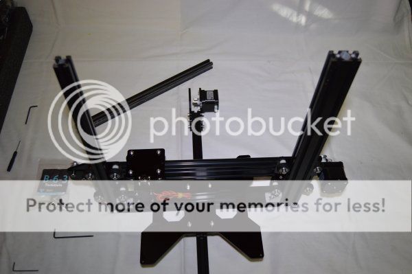
Next is the Z axis left and right parts.
I skipped the table assembly and moved to the frame.
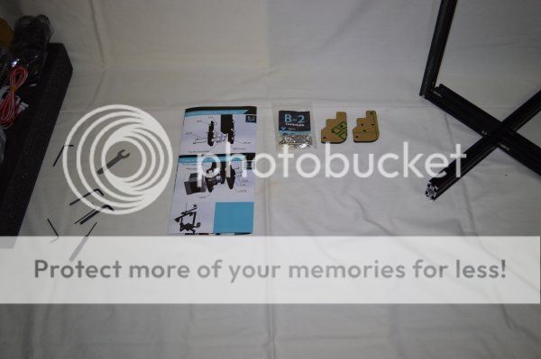
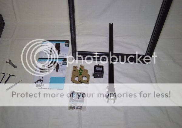
With the bottom, left and right frame profiles placed together, the front Y axis part is next to be built.
The back Y part is next. Some users advised to place the table part before assembling the final Y part but i preferred to leave that for later.
It is easier to place the table part at this point but it can be done later and without it i have more space to work.
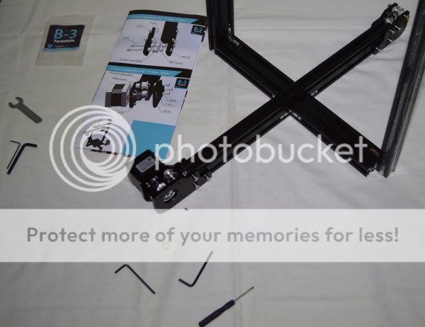
The assembly manual shows that the Y motor is mounted at the right side but this is wrong.
I only noticed this after the machine was assembled and i homed the axis. The Y axis was moving the wrong way (to the front).
The correct home position is at the back and therefore the motor must be mounted at the left side so that the Y axis can move the right way.
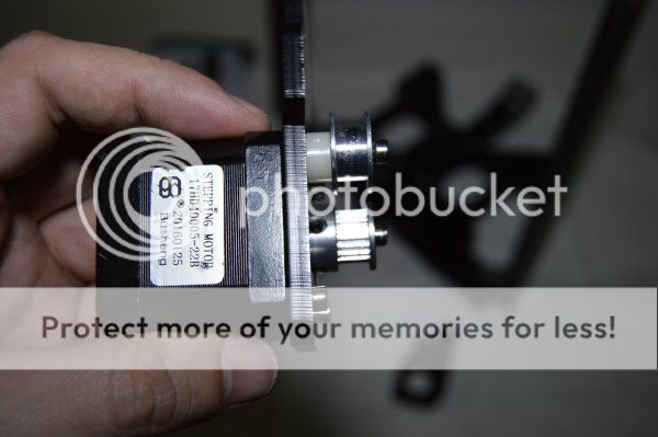
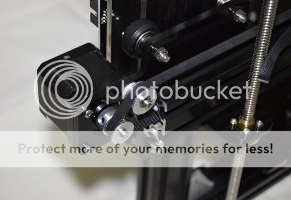
The inertia wheel must be placed first so that the pulley can be fasten aligned. The manual also shows the pulley assembled up side down but this is not correct because the motor shaft is not long enough and the lock screw is half off. I placed the pulley up side up and everything is correctly aligned.
The table part can be assembled in the meantime. When placing the table in place and after sliding down the X/Z bar ( next step ) i noticed that the table was not parallel to the bar, in fact, it was very far off. Because of that i had to remove the table and check all the bearing/pulley assembly and their heights. I also noticed that the adjustable pulleys had different heights from the fixed ones. To fix this issue i had to install very thin washers so that all 4 pulleys had the same height. With this i got the table parallel to the bar.
The Z/X mechanism can now slide down into place.
The top bar will secure the frame. At this point we should loosen the left and right Z parts because the side bars might not be correctly perpendicular. The top bar sides must match the left and right sides. Once the top bar is fasten in place we can adjust the position of the left and right parts.
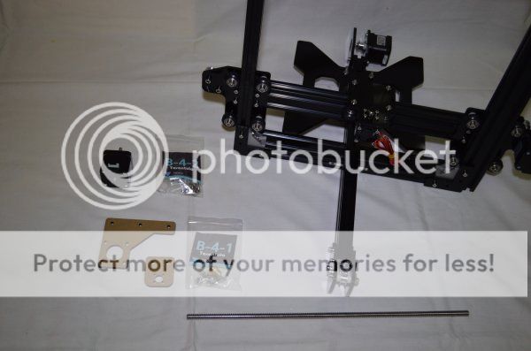
With the top bar in place we can assemble the Z motor mount and leadscrew.
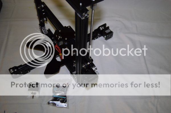
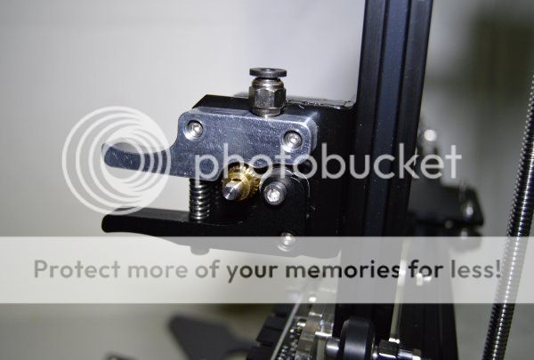
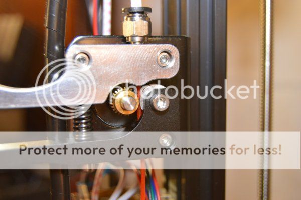
The extruder is also not mentioned in the assembly manual but is not hard to figure out how to assemble it.
The position of the extruder is not clear from the pictures but at the end i placed half way between the controller board and the top bar.
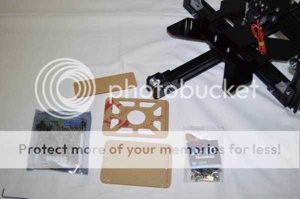
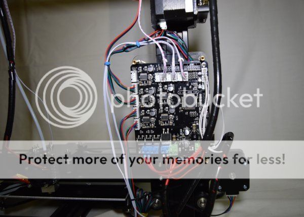
Next i placed the controller board in place.
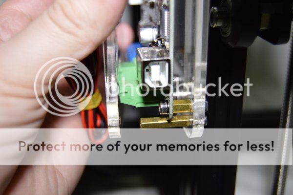
The standoffs for the controller front plate came too short. I had to buy longer ones but to test the machine we can use the long screws and these standoffs to hold the front plate in place. I decided to place it because of the fan. I didn't want to test the machine without any fan over the board. I don't know if the board heats up too much but it's better be safe than sorry.
I would prefer to finish the mechanical stuff before starting with the wires so i installed the belts before the endstop switches.
The belt goes through the frame and its secure with plastic ties (also provided). The extra belt must be cut.
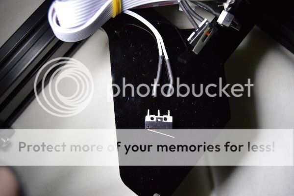
i noticed that, when handling with the switches, one fell off on my hand. The solder was not enough so i had to check every one before assembly.
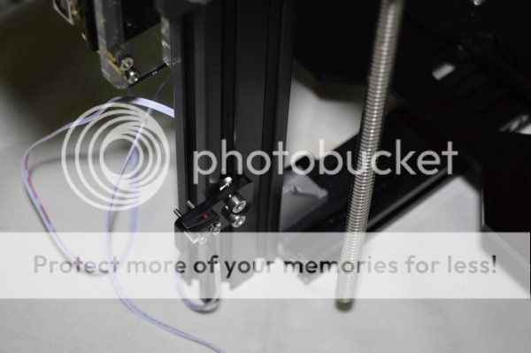
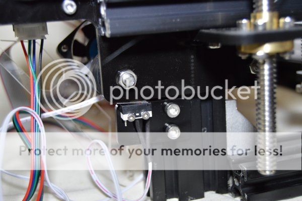
The Z endstop is installed at the right side behind the frame. Once more, the assembly manual does not mention anything about the endstops locations.
The final position for the Z endstop must be set later on after the table is leveled.
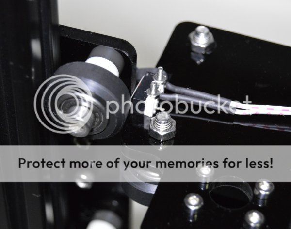
There are 2 small screws on the X part at the left side and this is were the endstop must be placed. There is not enough room to place the 2 screws with this X part in place so i had to loosen the bearings so i could lift it a bit to place the screws in. The nuts must be correctly fasten so that the screw heads don't touch and scratch the frame.
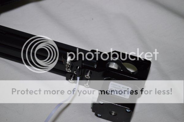
The Y endstop is placed at the back. It can be placed on the right side or the left side but i chosen the right side because it is much easier to root the wires this way.
Last but not least i placed the aluminium print bed. For me this should be the last assembly step because of the table wires.
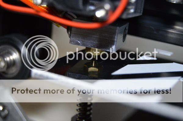
Leveling the table is very important. The bottom screws must be adjusted so that all four corners are at the same distance from the nozzle.
To do that we must move the Z almost all the way down and move the X and Y back and forth when adjusting. Be careful not to scratch the table with the nozzle when moving the X and Y. I noticed that the aluminium print bed is not perfectly flat and at the center i got a higher distance to the nozzle. The only way to fix this is to get a glass the same size of the table and place it on top of the table, level it with the glass and use it always. The final step is to adjust the endstop. I had to home the Z a few times to adjust the best position.
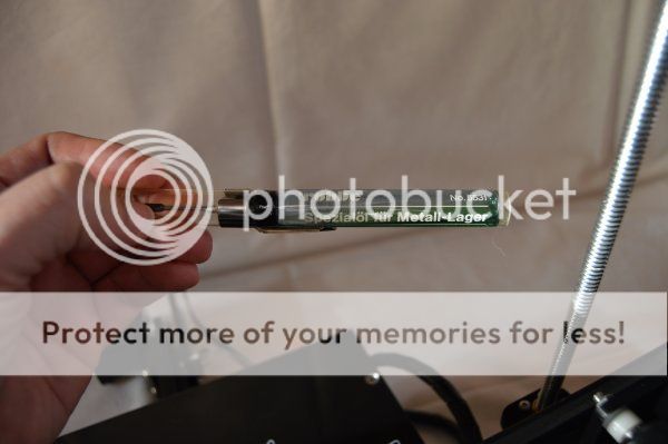
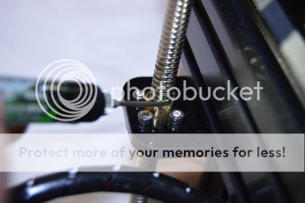
The Z leadscrew is the only thing that needs to be lubricated. I used a special oil for metal that i use with my RC helicopters.
Just added some drops and then moved the Z up and down to oil the entire leadscrew.
I rooted the wires so that the axis would not touch or pull any of them.
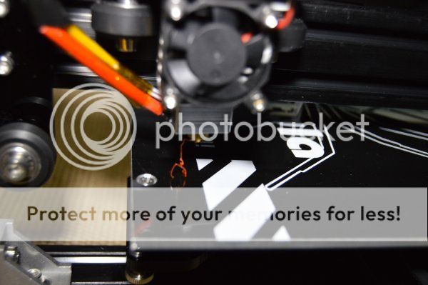
It's time to test the printer! Took the filament rool out and pushed through the extruder and all the way to the heater.
Heated the nozzle and pushed manually the filament until i could see plastic coming out from the nozzle.
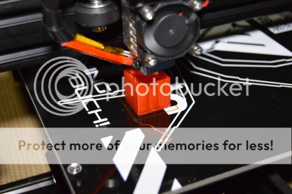
The first print should be the calibration cube of course.
I installed the cura software, configured the settings, downloaded the 20mm calibration cube and started my print.
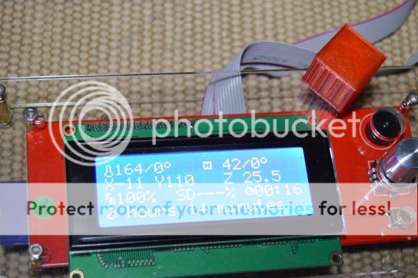
At the end, the display shows the time spent (also the cura software shows this before printing).
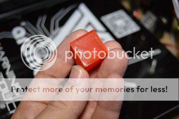
For my first print, the cube does not look too bad. There are many settings that need to be tweeked to improve the quality.
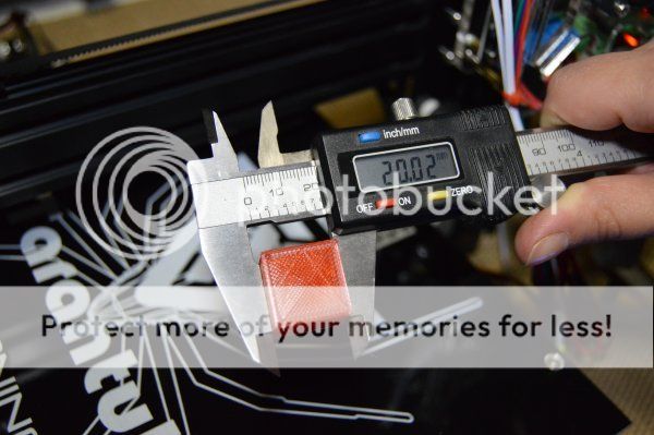
Measuring the sides i got the 20mm i was looking to get out of the calibration cube.
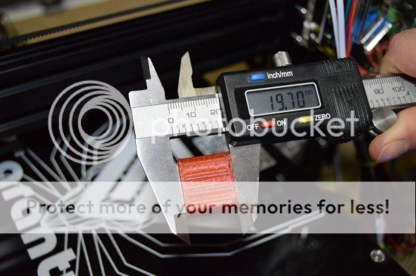
The height, however, was a bit under the 20mm. The problem might be with the first layers and not the Z stepping.
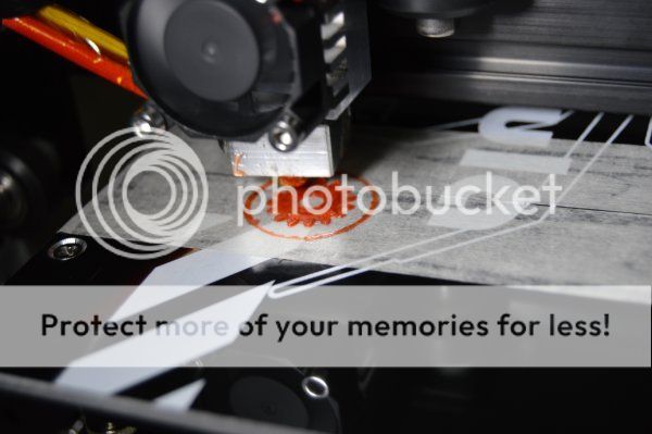
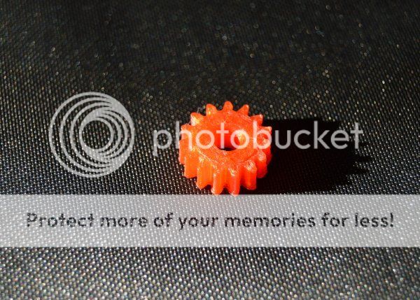
For my second print i decided to print a small gear.
The final result was not bad also but it could be much better. A couple of teeth came out far from perfect.
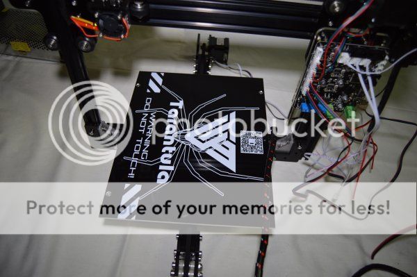
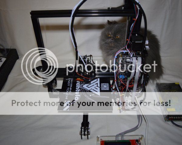
This is the look of the printer once finished. Opps...how did Becky (my persian cat) got there so fast?
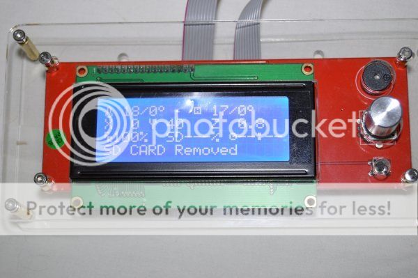
This is the information we get from the display. We can see the temperature of the nozzle and table, X,Y and Z coordinates and print status.
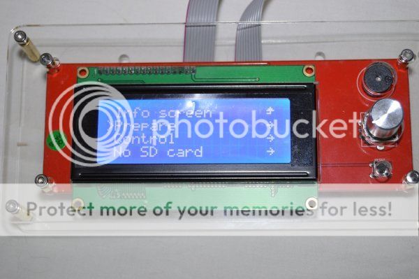
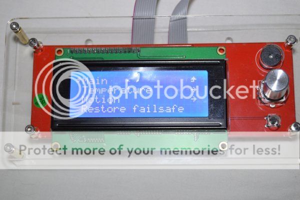
Pressing the rotary switch we enter the menu.
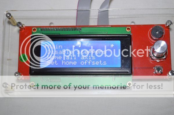
Prepare submenu will let us, for example, move the axis and home the axis.
We can also disable the steppers (so we can move them by hand) and set home offsets.
In control submenu we can set the table and nozzle temperature, adjust speeds and accelerations, etc.
After my second print i got my nozzle clogged. I tried some techniques used from other users like cold pull out of the filament or raising the temperature of the nozzle and push the filament in but no luck.
The only thing that worked was to buy a very thin needle (less than 0.4mm) and insert it into the nozzle while hot.
It's also a good practice to have a couple of spare nozzles just in case.
I don't know why the nozzle clogged just after only two prints but i've been told that clogged nozzles is a common thing.
I also recomend to install extra endstops. The switches can be connected to the X+,Y+ and Z+ connections on the board.
These switches are easy to find but the connectors maybe harder to get.
Good online shops like Farnell or RS have these connectors.
To install the X switch, we can use strong double side tape.
To install the Y and Z switches, i recomend to print a couple of switch holders like the original ones.
I have designed this part so that it can be printed.
The STL file can be downloaded here:
NOTE: For some reason, CURA software displays the part very small. To print the correct size you must scale up x10 so that the thickness of the piece is 4mm.
To resume things, i think that this is a fantastic machine for the price.
Too bad that the assembly manual is very poor and thank good for the internet.
Some parts need special attention like the bed parts and many parts that use regular nuts should use lock nuts instead.
Also there are many adjustments that need to be made and settings that need to be set to archive a good quality print.
VIDEOS:
Step 0 - Unboxing: youtu.be/M7dgI0bjgcw
Step 1 - X carriage: youtu.be/QENLe4ibkMQ
Step 2 - Z axis: youtu.be/sC6SSWaDn8o
Step 3 - Table: youtu.be/PCvILpUuogw
Step 4 - Frame: youtu.be/7DSIoS0BhMo
Step 5 - Y axis front: youtu.be/2XycaBD3Hjo
Step 6 - Y axis back: youtu.be/WQzEMX6ji-4
Step 7 - X and Z assembly: youtu.be/e7DICy_kbPE
Step 8 -Z motor and leadscrew: youtu.be/FS_ZhlMcYlE
Step 9 - Extruder: youtu.be/PNZCv1qfVRQ
Step 10 - Board: youtu.be/3q26Mmp68OI
Step 11 - Belts: youtu.be/OlcfF5_AD7E
Step 12 - Endstops: youtu.be/XdOd7iH_EsQ
Step 13 - Motor connections: youtu.be/NVrdtbs1iQE
Step 14 - Display: youtu.be/f9UQV3Gz-0w
Step 15 - Hotend: youtu.be/30h8QougL3Q
Step 16 - Hotbed: youtu.be/StVc6PLe_lk
First power on: youtu.be/AFdoYxoxVqQ
First print: youtu.be/faH9sjsmok8

