![]() A ideia deste projecto surgiu-me quando um dia estava a aceder remotamente ao meu PC para consultar uns trabalhos e imaginei que desta forma e ligando uma webcam poderia ver o que os meus gatos andariam a fazer quando sozinhos. No entanto precisava de algo mais pois a webcam pousada no topo do monitor não iría dar uma visão geral da divisão. Foi nessa altura que me lembrei de construir um circuito que permitisse movimentar a webcam em várias direcções.
A ideia deste projecto surgiu-me quando um dia estava a aceder remotamente ao meu PC para consultar uns trabalhos e imaginei que desta forma e ligando uma webcam poderia ver o que os meus gatos andariam a fazer quando sozinhos. No entanto precisava de algo mais pois a webcam pousada no topo do monitor não iría dar uma visão geral da divisão. Foi nessa altura que me lembrei de construir um circuito que permitisse movimentar a webcam em várias direcções.
![]() The idea for this project came when one day i was working with my PC remotely to access some projets and i realized that i could connect my webcam and see what my cats where doing when left alone in the house. However i needed more because with the webcam placed on top of my monitor staying still wasnt giving me the entire picture of that room. At that time i thought about designing a circuit that would allow me to change the camera angle.
The idea for this project came when one day i was working with my PC remotely to access some projets and i realized that i could connect my webcam and see what my cats where doing when left alone in the house. However i needed more because with the webcam placed on top of my monitor staying still wasnt giving me the entire picture of that room. At that time i thought about designing a circuit that would allow me to change the camera angle.
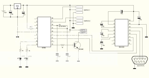
O circuito inclui um microcontrolador 16F88 com cristal de 20Mhz e um max232 para ligação ao PC.
Tem 3 saidas sendo duas para controlar dois servos ( rotação e inclinação ) e uma outra que pode controlar um dispositivo externo.
Como dispositivo externo liguei o meu candeeiro led para iluminar a área caso seja preciso.
The circuit includes a 16F88 microcontroller running with a 20Mhz oscillator and a max232 for comunicating with the PC.
It has 3 outputs where two of them are for controlling 2 servos ( pan and tilt ) and other for controlling an external device.
For the external device i'm using my led lamp that will be very usefull to iluminate the room when needed.
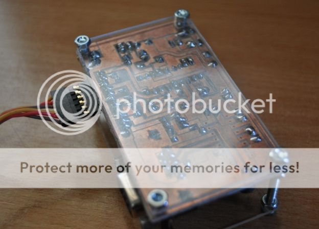
A placa de circuito impresso foi construida na minha CNC caseira.
The printed circuit board was made using my homemade CNC.
Neste circuito resolvi experimentar uma ideia que tinha visto na internet sobre imprimir o desenho da placa e colocar na superficie superior.
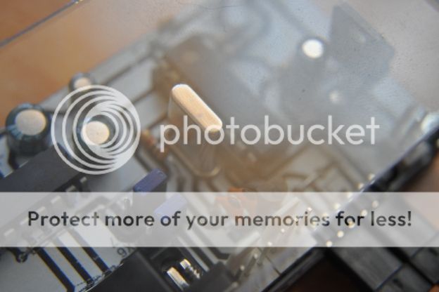
A ideia original é ajudar na colocação dos componentes. A minha ideia é meramente estética.
O resultado não ficou nada mal, mas ficaria melhor se a impressão tivesse sido a cores em vez de preto e branco.
For this project i decided to try an idea that i have seen on the internet about printing the circuit board design and place it on the upper surface of the pcb.
The original idea is to guide the person when installing the components on the board. My idea is just cosmetic.
The result turned out to be ok but it would be better if the sheet had been printed in color instead in black and white.
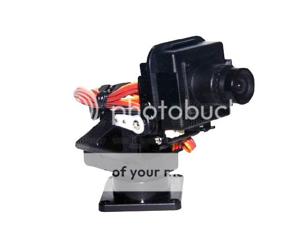
Da ebay comprei o suporte de câmera.
Neste suporte colocam-se dois micro servos para fazer os movimentos de rotação e inclinação.
I bought the camera mount from ebay.
This camera mount needs two micro servos to operate the pan and tilt moviments.
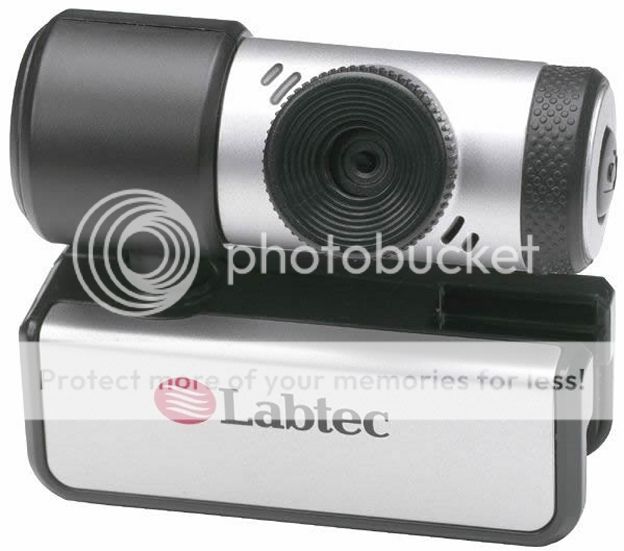
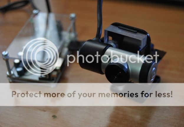
A webcam que usei foi uma Labtec Notebook.
Esta câmera é pequena e pesa menos de 11g o que a torna excelente para ser usada no suporte.
The webcam used was a Labtec Notebook.
This webcam is small and weighs less than 11g which makes it perfect for this camera mount.
O suporte porém foi desenhado para umas pequeníssimas câmeras ( não webcam ).
This camera mount was designed for those small video cameras ( not webcam ).
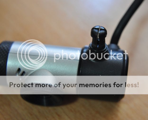
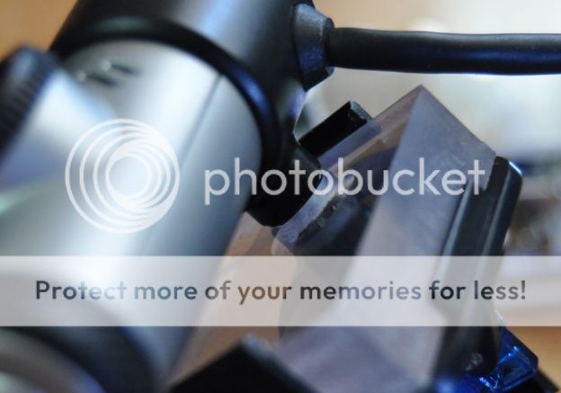
Retirando a base da webcam a câmara possui um pequeno eixo plástico.
Once removed the webcam bottom part we can see the plastic fixing side.
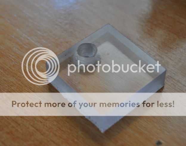
De volta á CNC cortei um pequeno quadrado de um pedaço de policarbonato de 10mm.
Back to my CNC i milled a small 10mm thick policarbonate square.
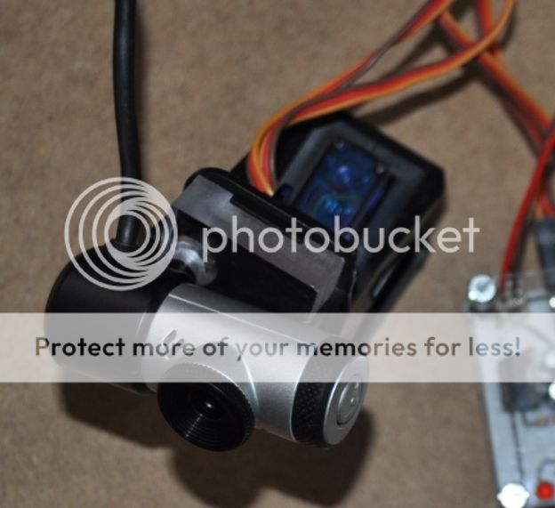
Este pedaço de policarbonato encaixa perfeitamente no suporte.
O furo permite o encaixe da webcam.
This small piece of policarbonate fits perfectly and the hole is for the webcam.
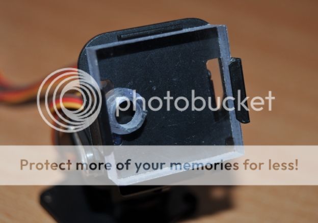
O furo teve de ser corrigido na face traseira, ou seja, tive de contruir uma pequena "caixa" no furo para a parte mais larga do eixo plástico da webcam.
Desta forma o encaixe da webcam ficou perfeito.
I had to correct the hole on the backside creating a slot for the larger end of the camera fixing part.
This way the webcam fits like it was factory made.
Também é possivel colocar a webcam na posição horizontal ou vertical dependendo do local onde se instala o suporte.
It's also possible to install the webcam in a vertical or horizontal position depending were the camera mount is placed.
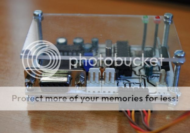
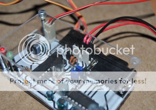
Também na CNC cortei duas placas de policarbonato de 2mm e fiz uma espécie de caixa simples.
Also in my CNC machine o milled two 2mm thick policarbonate plates and created a kind of transparent enclosure.
Apesar de não ter ficado perfeito, esta primeira montagem com placas de policarbonato ficou, na minha opinião, esteticamente bonita.
Although it is not perfect, my first tryout with the policarbonate plates is, in my opinion, visually atractive.
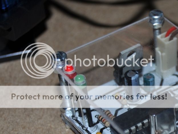
Dois leds indicam o estado das comunicações.
Um led para o RX e um led para o TX.
Two leds light up while data is being transfered.
One led is for RX and the other led is for TX.
Na foto abaixo, a ligação ao PC foi feita pela ficha molex de 3 pinos.
Os 2 jumpers permitem escolher o método de transferência de dados.
The picture bellow shows the comunication link using the 3 pin molex connector.
The 2 jumpers allow choosing the data transfer method.
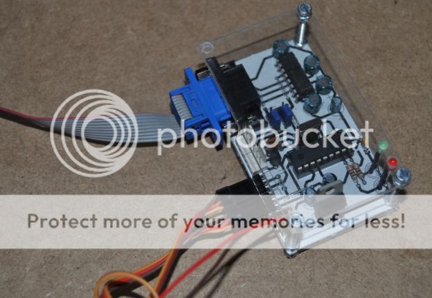
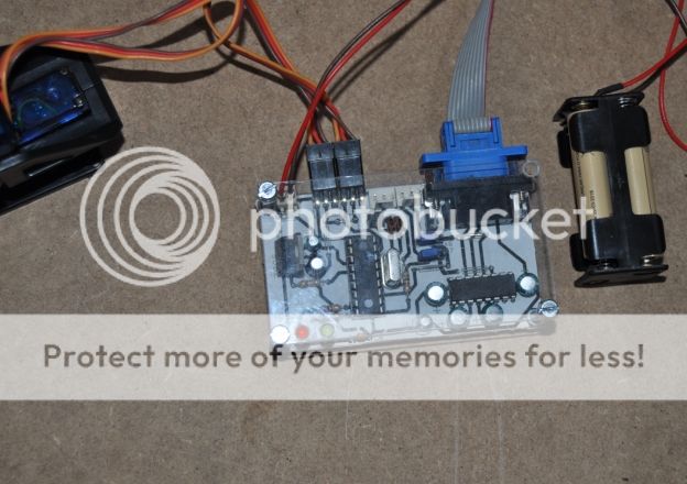
Na foto seguinte a ligação ao PC foi feita pela ficha D-Sub 9.
The next picture shows the data link with the PC being made using the D-Sub 9 connection.
Todo o conjunto é relativamente pequeno e como a comunicação da placa com o PC é feita pela porta série, ou seja, não precisa de instalar drivers nenhuns.
The entire set is small and because the comunication between the board and the computer is made using the serial port, no driver instalation is needed.
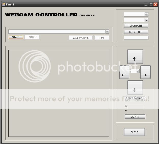
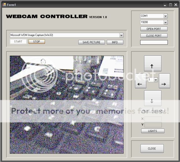
Do lado do computador, desenvolvi uma aplicação em Visual Basic para comunicar com o microcontrolador.
From the computer side, i've developed a software application written in Visual Basic to communicate with the microcontroller.
No programa é possivel escolher a porta e a velocidade. Para isso coloquei duas comboboxes.
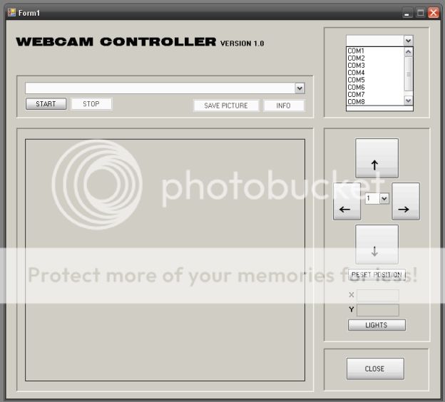
Na primeira escolhemos a porta com que irá comunicar com a placa.
In the form it's possible to choose the com port and baudrate. For that i placed two comboboxes.
In the first one we choose the com port that will be connected with the microcontroller.
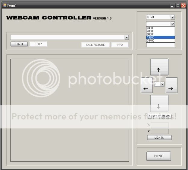
Na segunda combobox escolhemos a velocidade ( Baudrate ).
The second combobox is used to choose the baudrate.
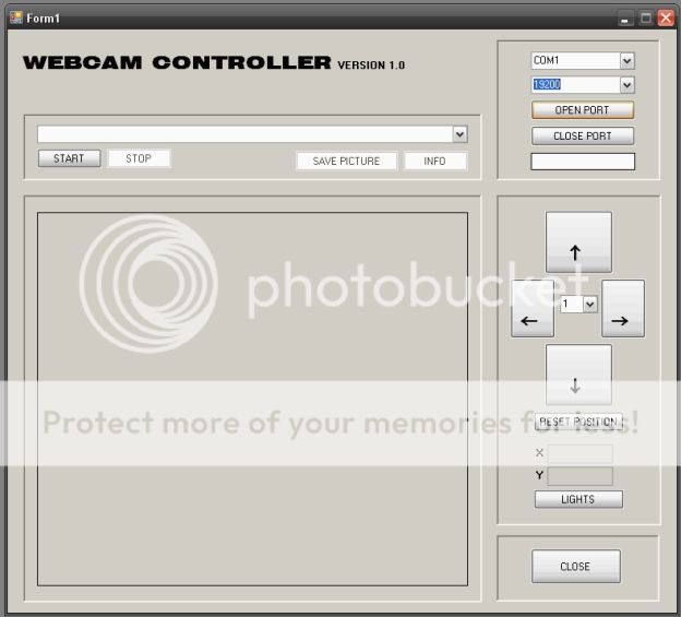
Depois destes dois parâmetros escolhidos é só carregar no botão "Open Port" para abrir a porta, neste caso, a COM1.
After setting the parameters the "Open Port" button must be pressed for the software to open the comunication port, which in my case is COM1.
Coloquei também outra combobox para escolher, caso haja mais que um, o dispositivo de captura de imagem.
Premindo o botão "Start" a imagem aparece.
Também é possivel gravar imagens da webcam através do botão "Save Picture".
I've also placed another combobox to choose, if there are more than one, the video capture source.
Pressing the "Start" button the image comes up.
It's also possible to capture a frame from the webcam by pressing the "Save Picture" button.
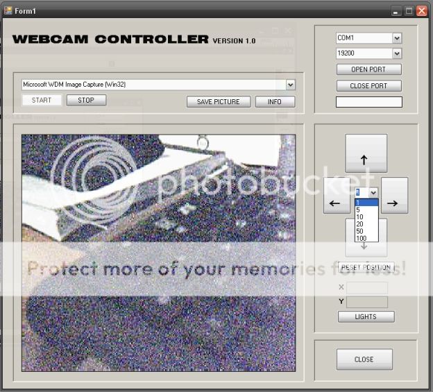
Também coloquei uma combobox onde se pode definir várias velocidades de movimento dos servos.
São 6 as velocidades e estão pré-definidas.
Next to the moviment buttons is another combobox where we can set one of six different servo speeds.
These speeds, or steps as you will, are pre-defined.
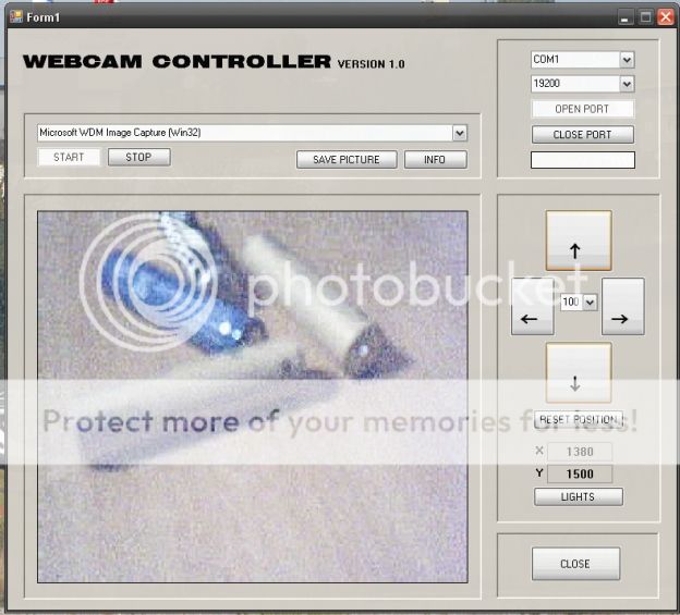
Usando os botões de movimento, as posições X e Y são sempre actualizadas.
Usando o botão "Reset" movimenta automaticamente os servos para a posição central.
Using the moviment buttons, the X and Y positions are updated.
Pressing the "Reset" button will make both servos move to their center position.
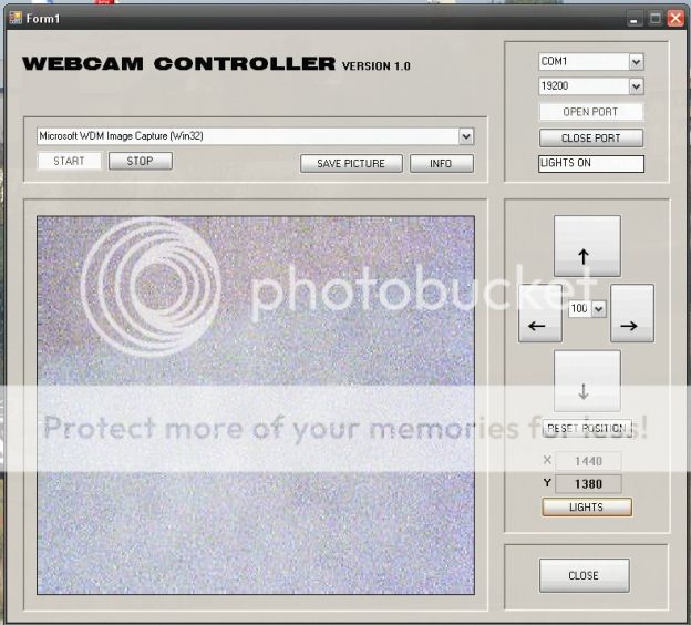
Quanto ao botão "Lights" permite activar ou desactivar a saída extra que no meu caso liga e desliga o candeeiro de leds.
A informação "Lights ON" ou "Lights OFF" aparece na janela por baixo do botão de fechar a porta.
About the "Lights" button it will turn the extra output on and off which in my case will turn on and off my led lamp.
The information "Lights on" or "Lights off" will appear in the textbox under the "Close port" button.
Desta forma consigo, acedendo remotamente ao PC com um software de monitorização como o VNC ou TeamViewer, ligar a webcam e fazê-la rodar ou inclinar e assim verificar o estado da minha casa á distância.
This way, using a remote access software like VNC or Teamviewer i can access my PC remotely, turn on the webcam and make it rotate or tilt to check how things are in my house when i'm not there.


