![]() O método de fabricação de PCIs que usava antes de adquirir a máquina CNC era litográfico e funcionava da seguinte forma:
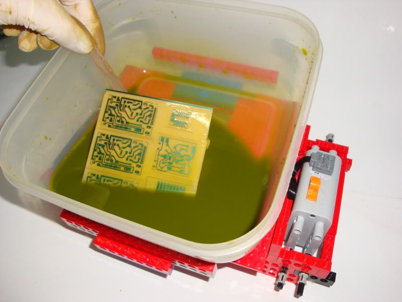
O método de fabricação de PCIs que usava antes de adquirir a máquina CNC era litográfico e funcionava da seguinte forma:
Primeiro imprimia o desenho da placa numa folha de acetato.
Essa folha era colocada por cima de uma placa foto sensível e colocada sob luz UV durante uns minutos.
De seguida essa placa era submersa numa solução com soda caustica para retirar a pelicila foto sensivel que ficou "danificada" com a luz UV.
A placa era depois submersa numa solução com ácido pre-coloreto de ferro.
Após uma lavagem para retirar os quimicos era necessário recortar a placa e por último furar os pads.
![]() The PCB manufacturing method i used before buying my CNC machine was the lithography method and worked as follows:
The PCB manufacturing method i used before buying my CNC machine was the lithography method and worked as follows:
First i printed the board design on an acetate sheet.
This sheet was placed over a pcb with a light sensitive coat and placed under UV light for several minutes.
The pcb was then immersed in a solution of caustic soda to remove the photo sensitive material that was "damaged" with the UV light.
The pcb was then immersed in a Ferric Chloride solution to remove the copper.
After the copper being removed i then washed the pcb to remove the chemicals and then i needed to cut the plate and finally drill the pads.
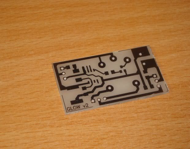
O resultado final era muito bom e com este método consegue-se muito boa resolução com vias muito finas mas demora imenso tempo a fabricar e dá imenso trabalho.
The result was very good and with that method i could archieve a very good resolution with very fine lines but it is very time consuming and gives a lot of work.
Tenho publicado todo este trabalho em mais detalhe aqui:
I have all the details of that procedure here:
ruijc.webnode.com/products/pcis-pelo-metodo-tradicional-making-pcbs-with-the-traditional-way/
Uma das razões que me fez investir numa máquina CNC foi conseguir fabricar placas de circuito impresso rápidamente e facilmente.
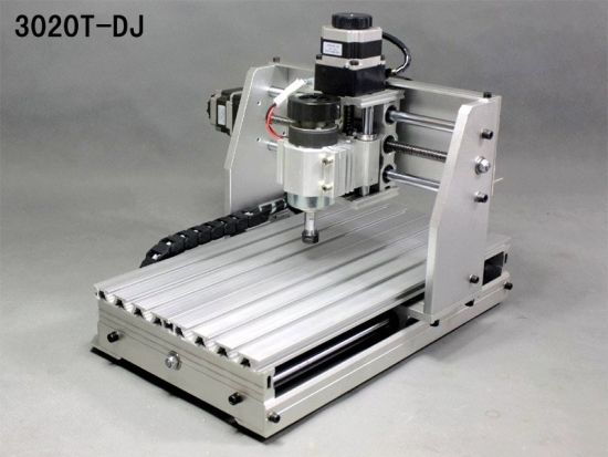
A CNC que possuo neste momento é uma 3020T-DJ comprada na ebay mas com várias alterações feitas por mim.
Os motores de passo são mais potentes que os de origem e o controlador foi totalmente construido de raiz e equipado com um driver Gecko G540.
One of the reasons that made me invest in a CNC machine was to be able to manufacture printed circuit boards quickly and easily.
The CNC machine that I have right now is a 3020T-DJ which i bought on ebay but with several modifications made by me.
The stepper motors are more powerful than the ones that came with the machine and the controller is totally made from scratch and equipped with a Gecko G540 driver.
O método de fabrico com uma máquina CNC é completamente diferente mas, apesar de ser muito mais fácil e simples, requer alguns cuidados para o resultado ser satisfatório.
The method of making pcbs with a CNC machine is completely different but, despite being much easier and simple, it requires some tweeks for the result to be satisfactory.
Enquanto que, com o processo quimico é retirado todo o material de cobre que não será utilizado, com o método de gravação com CNC é apenas feita a separação das pistas também conhecido como Isolation Milling.
While with the chemical process the copper material that will not be used is etched away, with the CNC engraving method only an isolation between tracks is created which is also known as Isolation Milling.
De seguida vou explicar como faço as placas. Existem outras maneiras e ferramentas diferentes para fazer as placas com CNC mas cada um tem a liberdade de escolher como quer fazer.
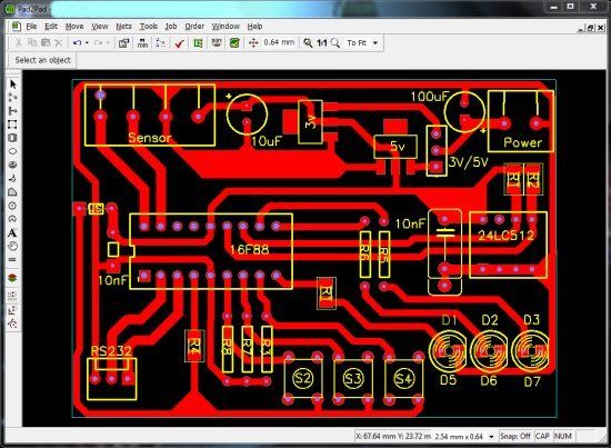
Como é obvio, começo com o desenho da placa. Para desenhar a placa uso o software Pad2pad que é gratuito e muito simples de usar.
I will explain how i make my PCBs. There are many other ways and with different tools to make PCBs with CNC machines but each one is free to choose how to do them.
As is obvious, i start with the board design. To draw the board i use the Pad2Pad software which is freeware and very simple to use.
Uma vez o desenho concluido, escondo a silk layer para apenas serem visiveis as pistas.
Once the drawing is done i hide the silk layer so that only the tracks are displayed.
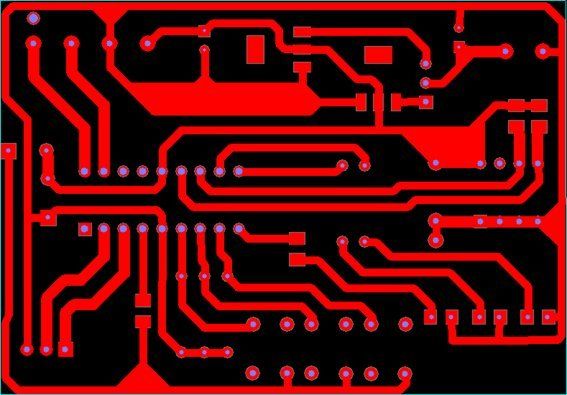
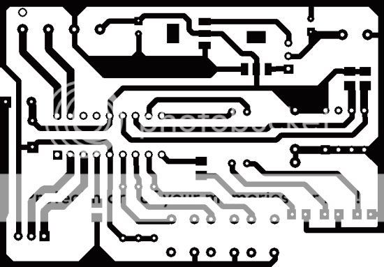
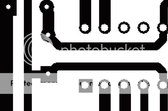
Capturo a imagem e exporto para um software de edição de imagem. Qualquer software serve e apenas será necessário efectuar edições simples. Será necessário primeiro substituir as cores das pistas e fundo.
I capture the image and then I export the image into an image editing software. Any image editing software will work since i only have to perform simple modifications to the drawing. First i will need to replace the colors of the tracks and background.
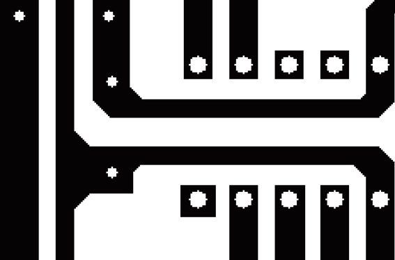
De seguida vou necessitar de modificar o aspecto das pistas e pads. Como todos os programas de desenho de PCI, eles criam os pads redondos ou rectangulares e não têm em mente o método de fabrico da PCI.
Como vamos usar uma fresa, é conveniente não só tornar o caminho mais acessivel mas também dar um acabamento melhor.
Then i'll need to modify the appearance of tracks and pads. Like all PCB drawing programs, they create round or rectangular pads and dont have in mind which method of manufacturing the pcb.
Because i will be using an endmill, it's better to provide an easy path and at the same time provide a better finish.
Desta forma elimina-se os pads redondos e corrigem-se as pistas.
This way i replace the round pads for the square ones and i fix the tracks.
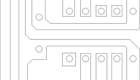
Uma vez o desenho corrigido, passa-se a imagem para o software que irá gerar o ficheiro gcode para a máquina cortar.
Neste software define-se também a profundidade de corte e outros parametros.
O software que uso é o Cut2D. Não é gratuito mas é o preço é muito acessivel e compensa pois é uma excelente ferramenta que uso não só para placas mas para qualquer trabalho na CNC.
Once the design has been adjusted,i need to transfer the picture into a software that will generate the gcode file for the CNC machine.
This software also sets up the cutting depth and other parameters.
The software I use is the CUT2D software. It's not free but the price is very affordable and it is worth the money because it is an excellent tool to use not only for PCBs but for any other work on the CNC.
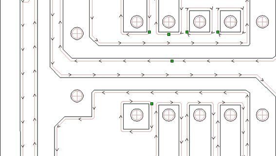
Da imagem ele cria vectores e com esses vectores podemos seleccionar como queremos cortar.
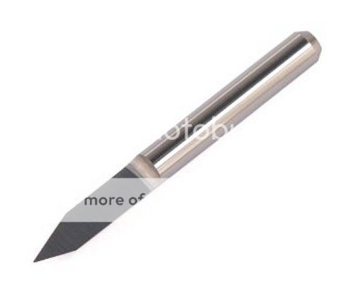
Seleccionando as pistas define-se que irá ser usado um bit em V de gravação e será maquinado pelo lado externo da linha.
Selecciona-se também a broca para perfurar os pads e a fresa para cortar a PCI.
From the image it creates vectors and with these vectors i can select how i want to cut them.
Selecting the tracks i will set that they will be engraved with one engraving V bit and by the outer side of them.
I also select the drill size to drill the pads and the endmill to cut the PCB.
No inicio comprei muitos bits V com vários angulos sendo a maior parte com 0.1mm.
Depressa descobri que a medida do bit deve ser o maior possivel, ou seja, se a distância mínima entre pistas do meu desenho for igual ou superior a, por exemplo, 0,4mm, significa que terei de usar um bit de tamanho não inferior a 0.4mm.
A maior parte das minhas placas usam bits de 0.3mm ou 0.4mm.
At my early runs I bought many bits V with multiple angles being the most of them of size 0.1mm.
Quickly i discovered that the bit should be as large as possible, so if the distance between the tracks of my design is equal to or greater than, for example, 0.4mm, it means that i will have to use a size of bit not smaller than 0.4mm.
The majority of my PCBs use bits with sizes 0.3mm or 0.4mm.
Outros parametros importantes são a profundidade de gravação.
Eu uso uma profundidade de 0.08mm a 0.1mm e como velocidade de gravação uso 3mm/seg.
É muito importante a mesa da CNC estar perfeitamente planarizada ou corre-se o risco de a marcação ficar com falhas.
A velocidade é lenta mas poupa um pouco a fresa de gravação fazendo-a durar mais.
Other important parameter is the cut depth of the engraving.
I use a depth of 0.08mm to 0.1mm and 3mm/sec as cutting speed. It is very important that the CNC table is planarized. If not the engraving will not be perfect.
The speed is slow but saves the engraving bit making it last longer.
Para os furos também uso uma velocidade vertical lenta mas desta vez não para poupar a broca mas para ter um furo mais perfeito.
For the holes i also use a slow vertical speed but this is not only to save the drill but also to have a better finish.
Para o corte exterior já posso usar velocidades maiores.
For the outer cut i can use higher cutting speeds.
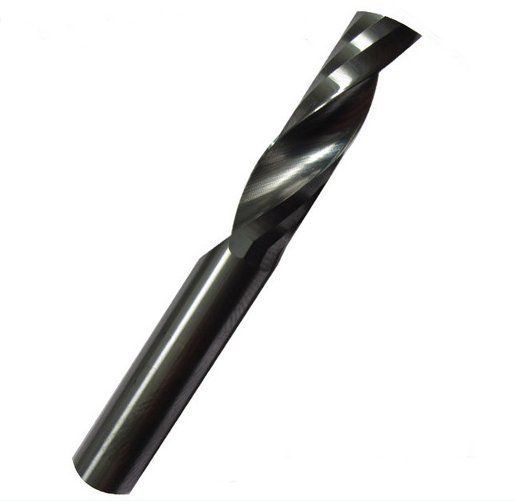
Normalmente para o corte da placa uso uma fresa de 1 lâmina desenhada para corte de acrilico.
Normally for the outer cut i use a single flute endmill designed for cutting acrylic.
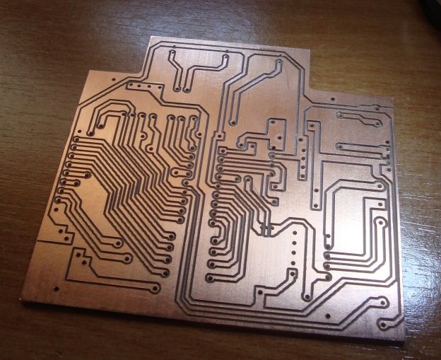
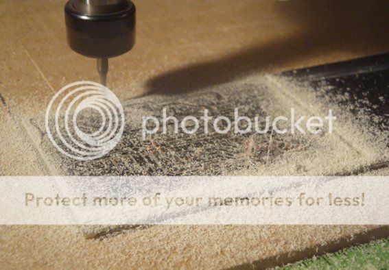
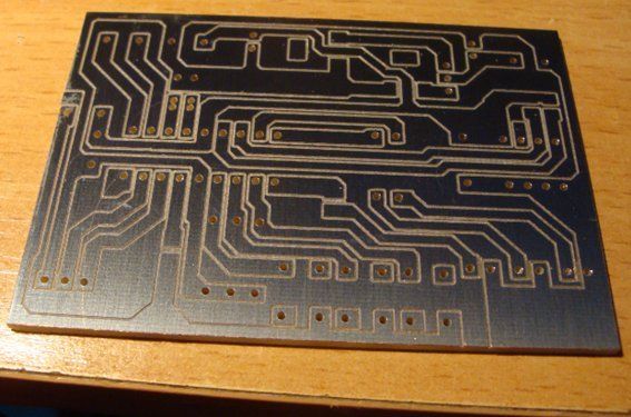
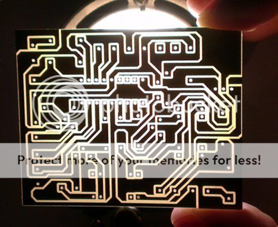
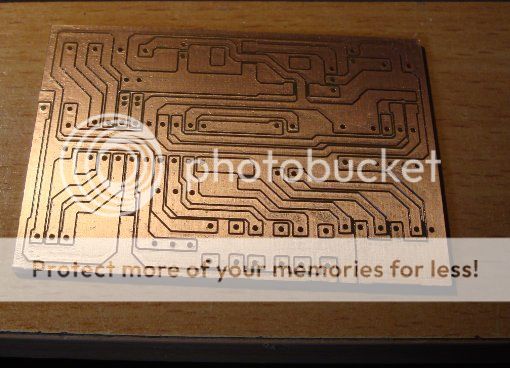
Na fotografia em baixo é possivel ver a placa acabada de sair da máquina sem qualquer retoque.
In the picture bellow it is possible to see the PCB after the outer cut and without any cleaning.
Se pensarmos bem, uma placa tradicional, como foi eliminado o cobre não utilizável, deixa-nos com bastante espaço para soldar.
If we think about it, on a traditional board, because the unusable copper has been etched, it leaves us with enough space for soldering.
No caso das placas feitas por este método, existe cobre a toda a volta logo é mais dificil aplicar a solda sem provocar um curto circuito.
Por isso é importante usar a fresa de maior dimensão possivel para se ter mais espaço entre pistas e facilitar a aplicação da solda.
In this case with isolation milling, the copper is all there so it can be tricky to apply the solder without causing a short circuit.
That is why is important to use the larger engraving bit possible so we can have more space between tracks and ease the application of solder.
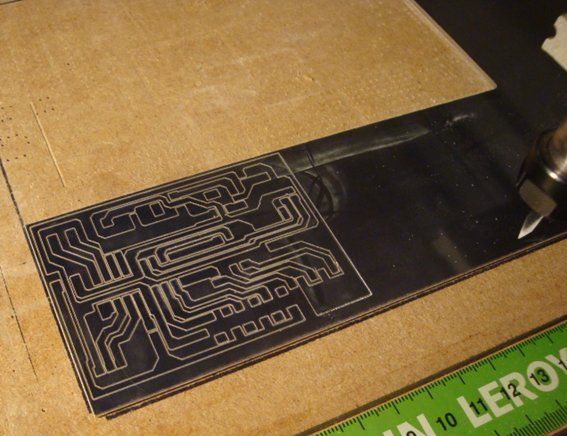
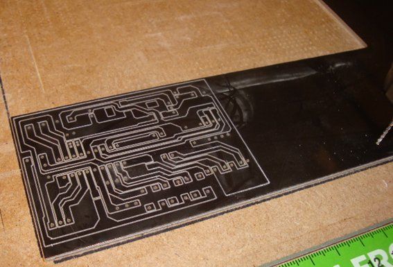
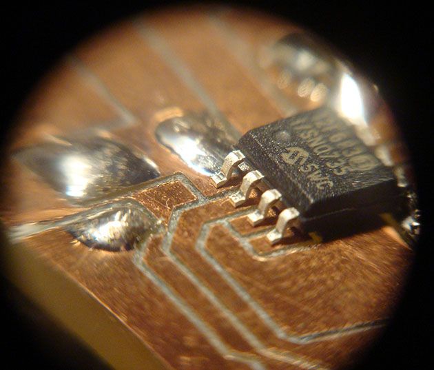
Em baixo está uma placa feita com uma fresa de gravação de 0.5mm e furos de 1mm.
Bellow is a PCB made with a 0.5mm engraving V bit and with 1mm holes.
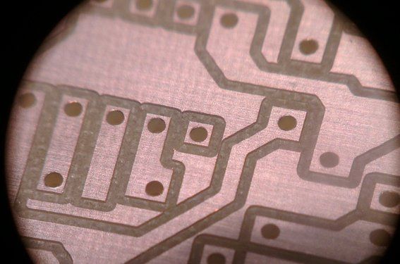
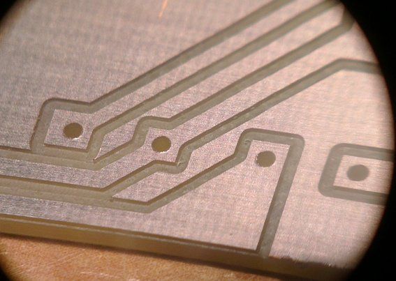
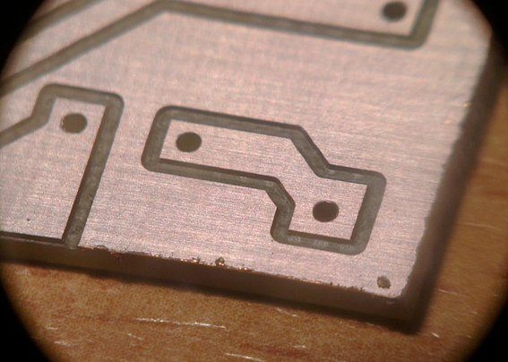
Em baixo estão algumas fotografias com detalhes dessa mesma placa.
Bellow are some pictures with details of that PCB.
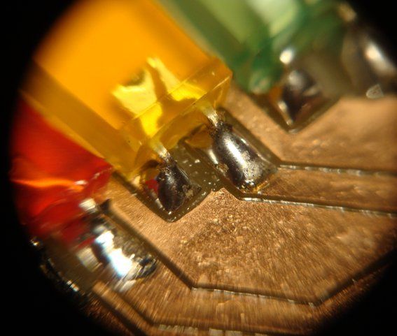
Na figura abaixo está um detalhe dos pads quadrados. Prefiro os pads quadrados pois fornecem mais área para a solda que os redondos.
The picture bellow shows the detail of the square pads. I prefer square pads because they have mode area to solder than the round ones.
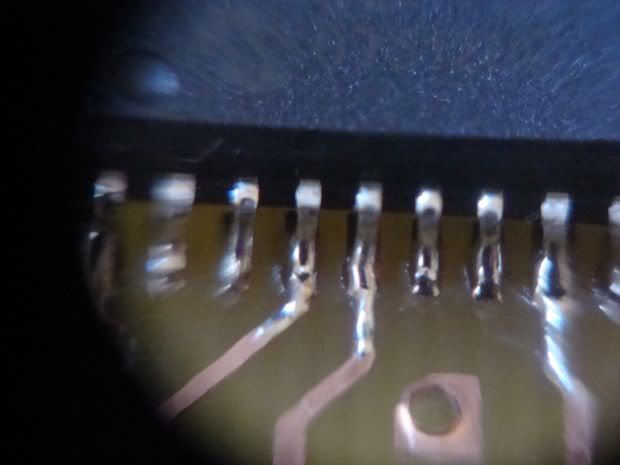
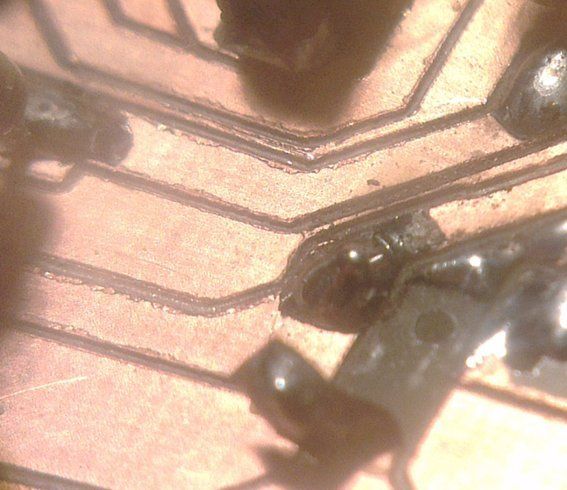
Na figura abaixo nota-se o único lixo acomulado do corte provocado pela fresa de 1 lâmina.
Este lixo sai facilmente com a unha.
The picture bellow shows the only debris found on the board after the outer cut from the single flute endmill.
This type of debris comes off very easly like with a fingernail.
Em baixo está um exemplo de um corte com problemas.
A fresa não conseguiu efectuar um corte limpo deixando muitas limalhas agarradas ás pistas.
Isto faz com que a placa tenha um aspecto horrivel e pode causar vários problemas como ruido e curto-circuitos.
Below is an example of a bad cut work.
The engraving bit could not make a clean cut leaving many filings and debris.
This makes the board have a horrible appearance and can cause several problems such as noise and short circuits.
Por esse motivo é preciso verificar sempre o estado das fresas de gravação e substituir sempre que necessário.
As minhas compro-as na ebay e são muito baratas. Podem ser de menor qualidade mas desde que se mantenha uma velocidade controlada e substitui-las regularmente compensa pois acaba por ficar mais barato comprar destas de qualidade inferior mas em grande quantidade ( compro aos conjuntos de 10 unidades ) que um modelo caro ( sim, porque este tipo de ferramenta não arranjo cá, ou seja, tenho sempre de mandar vir de fora o que encarece mais o artigo ) e que acaba por se degradar com o tempo também.
For that reason its a must to always check the status of engraving bit and replace when necessary.
My bits I buy them on ebay and are very cheap. They may be of lower quality but as long as i keep a controlled speed and handle them with care it compensates and ends up cheaper to buy these inferior but in large amounts ( i buy sets of 10 units) than an expensive model ( yes, because this type of tool is very hard to find them here which means that I always have to order them from UK or US and the shipping will add more money to the final price ) and that ultimately degrade over time as well.
Após a conclusão do trabalho na CNC tenho duas opções... ou soldo os componentes e no final aplico verniz protector ou então aplico um verniz protector que inclui fluxite antes de iniciar a colocação dos componentes. Este tipo de verniz ajuda na soldadura pois inclui fluxo e funciona como verniz final para protecção da placa.
Upon completion of the work on the CNC i have two options ... or i solder the components and then apply protective varnish or i apply a protective varnish that includes flux before soldering the components. This type of varnish helps the soldering process since it includes flux and works as final varnish protection.
Um método não usual que já usei foi deixar a camada fotosensivel da placa ( sim...também uso placas com pelicula foto sensivel pois tinha muitas em stock ) e usa-la como camada de proteção do cobre e fica com um tom esverdeado.
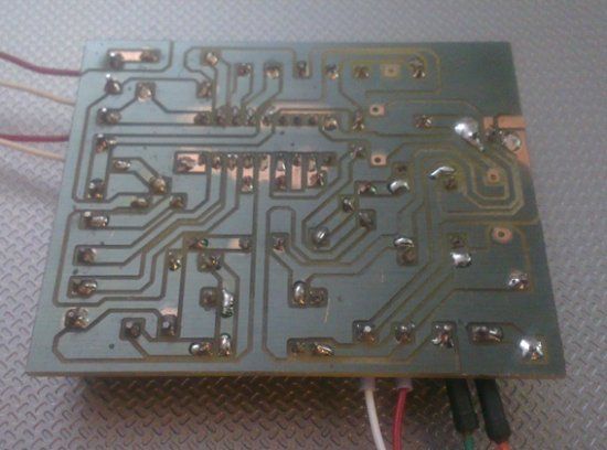
Em baixo está uma imagem de uma placa ainda com a pelicula foto sensivel. Apenas os pads foram limpos para ser aplicada a solda.
An unusual method I used some times was leaving the photosensitive layer of the board (yes ... i also use boards with photo sensitive film on my CNC because i have so many in stock) and use it as a copper layer protection and it gets a greenish look.
Below is an image of one of those board with the photo sensitive film. Only the pads were cleaned to better apply the solder.
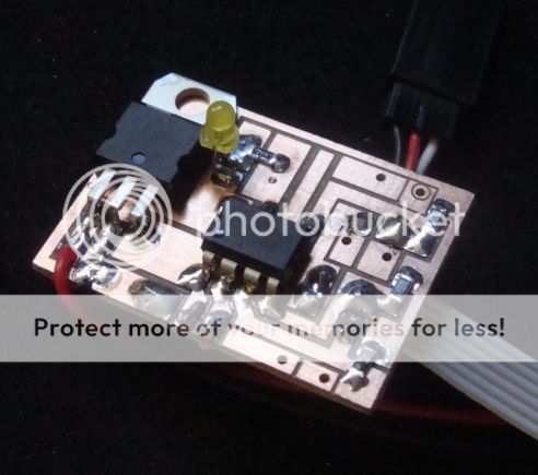
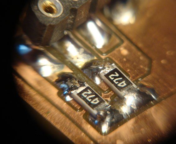
Em baixo alguns detalhes da board já com componentes soldados.
Bellow there are some details of the board with some components soldered.
Outro detalhe importante é a fixação da placa á mesa da CNC.
No inicio usava sempre clamps para fixar as placas mas por qualquer motivoo resultado não era perfeito.
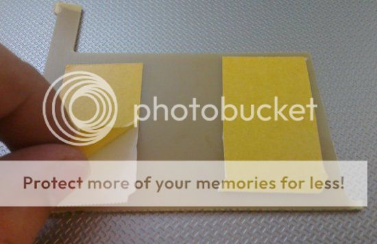
Aprendi que usando fita-cola de dupla face, além de fixar muito bem a placa, produz um resultado melhor.
Another important detail is how to secure the board on the table of the CNC.
At first i used clamps to secure the boards but for some reason the result was not so perfect.
I have learned that using double-sided duct tape, it holds the boards very well and produces better results.
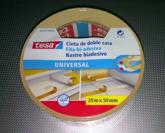
A fita que uso é uma fita muito fina da marca TESA e é forte e resistente. Também uso desta fita para fixar outros materiais como MDF, policarbonato e outros polimeros sem qualquer problema.
The tape I use is a very thin tape from TESA brand and is strong and sturdy. I also use this tape to secure other materials such as MDF, polycarbonate and other polymers without any problem.
Como referi no inicio, existem muitos outros métodos para fabricar PCIs numa máquina CNC sendo o mais popular desenhar a placa no software Eagle e exportar o ficheiro Gcode com o plugin PCBGcode.
Cabe a si escolher o o método mais indicado.
As I mentioned at the beginning, there are many other methods to manufacture PCBs in a CNC machine which the most popular is to design de board in Eagle software and export the Gcode file with the PCBGcode plugin.
It's up to you to choose the most appropriate method.
Pode também ler a minha análise á CNC que comprei aqui:
Next you can check my review of my CNC machine:
ruijc.webnode.com/news/cnc-3020t/


