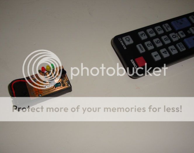
![]() Quem ainda não teve necessidade de testar um comando de Tv ou DVD?
Quem ainda não teve necessidade de testar um comando de Tv ou DVD?
Eu já e por várias vezes. A minha técnica favorita era pegar no telemovel e com a câmera apontada para o emissor infravermelho procurar a luzinha piscar. O telemóvel é uma excelente ferramenta para testar os comandos mas mesmo assim decidi fazer um pequeno circuito para testar os comandos.
![]() Who never had the need to test a TV or DVD remote?
Who never had the need to test a TV or DVD remote?
I have several times. My favorite technique was to take my mobile phone and with the camera pointed at the infrared emitter look for a flashing little purple light. The mobile phone technique is an way for testing the remote but still i decided to make a small circuit just to test the remotes.
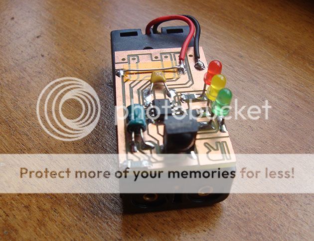
O circuito não necessita de muitos componentes...basta um microcontrolador, um receptor de infravermelhos e alguns leds para indicarem o nível de dados recebidos pelo comando. Funciona com qualquer comando desde que seja infra-vermelhos.
O microcontrolador que usei foi o 12F683 da Microchip em formato SOIC.
Apenas precisa de 2 pilhas AAA e consome apenas 0.8mhA em standby e 1.2mhA em detecção contínua.
The circuit does not require many components ... just a microcontroller, an infrared receiver and some LEDs to indicate the level of data received by the remote. It works with any remote that works with infrared.
The microcontroller I used was the 12F683 from Microchip in SOIC format.
Only need 2 AAA batteries and it's current draws is only 0.8mhA in standby and 1.2mhA in continuous detection.
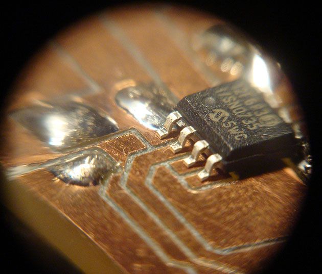
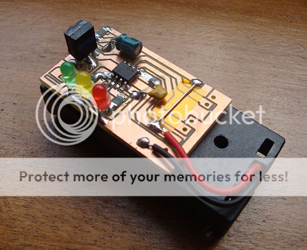
Como tem sido habitual, fabriquei a pcb na minha CNC. Uma vez que decidi usar um microcontrolador em formato SOIC, as pistas mais pequenas ficaram com uma largura de apenas 0.6mm.
Aqui está uma foto do detalhe de corte das pistas com o microcontrolador em posição ainda por soldar.
As usual, the PCB was made with my CNC machine.
Since I decided to use a microcontroller in SOIC format, the smaller tracks had to be only 0.6mm wide.
Here is a picture of the cutting detail with the microcontroller on its position before soldering.
Quando o circuito é ligado, o led vermelho acende. Isto indica que o circuito está ligado mas não está a receber nenhum sinal de infra-vermelhos.
Consoante o fluxo de dados de infra-vermelhos, ele acende os leds amarelo e/ou verde.
Se o fluxo de dados for contínuo, todos os 3 leds acenderão.
Caso o fluxo de dados esteja a ser recebido mas não continuamente acenderá apenas o led amarelo.
When the circuit is switched on, the red LED lights up. This indicates that the circuit is turned on but not receiving any infrared signal.
Depending on the received flow data, it lights the yellow and / or green LEDs.
If the data stream is continuous, all three LEDs light up.
If the data stream is being received but not continuously only the yellow LED will light up.
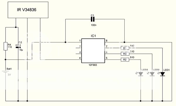
O esquema do circuito é muito simples.
The schematic of the circuit is very simple.
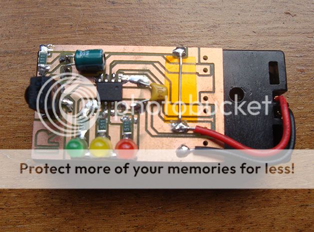
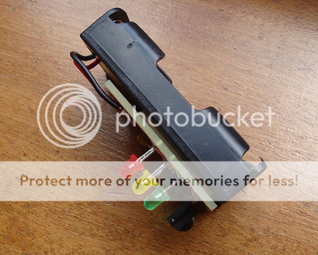
A placa está colada sobre um suporte de pilhas ( 2x AAA ).
The PCB is glued on top of the battery holder ( 2x AAA ).
Na parte trazeira da PCB existe uma saida RS232.
Não coloquei nenhuma ficha de ligação mas o microcontrolador está preparado para exportar os dados recebidos.
On one end of the PCB there is an RS232 output.
I did not soldered any connector but the microcontroller is ready to export the data received by the infrared receiver.
O receptor IR foi o V34836 da vishay.
O datasheet deste receptor pode ser consultado aqui:
The IR receiver i used was vishay V34836.
The datasheet can be found here:
www.vishay.com/docs/82489/tsop322.pdf
Como sempre aqui fica um pequeno video do testador a funcionar.
No video vou testar 2 comandos. O primeiro funciona sem problemas enquanto que o segundo está com as pilhas quase gastas.
As always here's a short video of the tester working.
In the video I will test two remotes. The first runs smoothly while the second has almost drained batteries.


